Categories
- Balance (11)
- Book (5)
- Chromatography (21)
- Clinical Trial (14)
- Engineering (49)
- FDA (4)
- Formulation Development (47)
- HPLC (20)
- Human Resource (14)
- Microbiology (51)
- Packing (26)
- Parenteral (5)
- Pharmacist (55)
- Pharmacoeconomics (44)
- Production (104)
- Qualification (4)
- Quality Assurance (80)
- Quality Control (206)
- Regulatory Affair (47)
- Validation (19)
- Warehouse (43)

Pharmaceutical Industry Profit Margin (Manufacturer to Retailers)
September 03, 2024

Online F1 and F2 Calculator
May 31, 2025

SOP for Forced Degradation Study
September 05, 2023

SOP for Calibration of Shimadzu UV–1800 UV Spectrophotometer
November 23, 2023

SOP for Operation of Shimadzu HPLC LC-2010 CHT
October 07, 2023

SOP for Conducting Acceptable Quality Levels
May 22, 2025
.webp)
SOP for Operation of Shimadzu HPLC (Prominence – i LC – 2030)
October 07, 2023
SOP for Performance Verification of the LCQ MS Detector (Finnigan)
PharmaInfo
February 19, 2024
OBJECTIVE
This SOP provides a guide on how to verify the performance of the LCQ MS detector to demonstrate that it is operating satisfactorily during normal operations. The verification includes checking the vacuum levels and electronic system and performing calibration and tuning for signal optimization. By performing a system check, the user will know at the start whether the instrument is operational or not, and there is less chance of interrupted work due to sudden instrument breakdown.
Performance verification will ensure the quality of the instrument and the measurements made.
SCOPE
This procedure applies to all types of determinations that involve the use of this instrument.
Checking the vacuum system levels is a prerequisite before analysis. The diagnostic test for the electronic system is done regularly or whenever there is a system failure. Calibration (using caffeine, MRFA and Ultramark 1621) and tuning (using reserpine solution) are performed periodically.
RESPONSIBILITIES
Any person who uses the instrument should perform the system check. If a problem is encountered during the check, inform the person responsible for the instrument.
INSTRUCTIONS
Verifying the System Vacuum Levels
The vacuum system level must always be checked before starting any analysis. Vacuum manifold pressures are measured by the ion gauge and convection gauge pressure. Check the vacuum manifold pressure levels as follows:
- On the desktop, double-click on the LCQ Tune icon to display the Tune Plus window.
- In the Tune Plus window, click on the vacuum button or choose Setup > Vacuum to display the vacuum dialog box. Verify that the ion gauge pressure is around 1 x 10⁻⁵ Torr and the convection gauge pressure is around 1 Torr. Record the values in the instrument logbook.
- If the pressure is too high, check whether the API flange is secured to the spray shield and check for loose connections. Pressures below these values may indicate partial or total blockage of the heated capillary. Clear the blockage on the heated capillary.
Verifying the Instrument Electronic System
The instrument's electronic system is verified by performing the diagnostic test. Run the diagnostic test as follows:
- On the desktop, double-click on the LCQ Tune icon to display the Tune Plus window.
- Click on the On/Standby icon to turn on the detector.
- In the Tune Plus window, select Diagnostics > Diagnostics to open the Diagnostics dialog box.
- Select the Graphs tab.
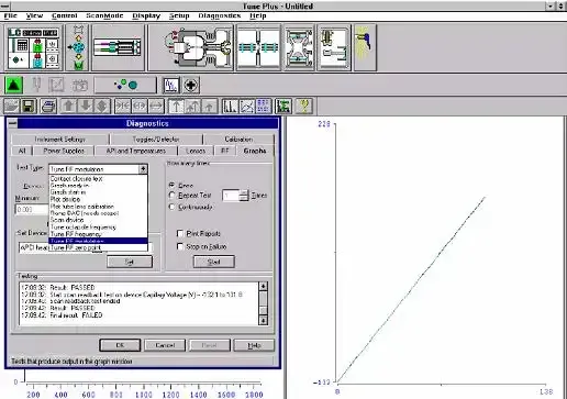
- Reposition the Diagnostics dialog box such that it does not block the Graph view as shown in Figure 1.
Figure 1. Diagnostics dialog box and Graph view
- Tune the octopole RF voltage as follows:
- In the Test Type text box, select Tune multipole frequency.
- In the How many times group box, select the Once option.
- Click on the Start button. A frequency function appears in the graph view as shown in Figure 2. The minimum frequency function should lie between 2400 and 2550 kHz.
- After the octopole tune program is finished, click on the Yes button to accept the multipole frequency.
Figure 2. Graph view for the octopole RF voltage tuning.
- Tune the ring electrode RF modulation as follows:
- In the Test Type textbox, select Tune RF modulation.
- In the How many times group box, select the Once option.
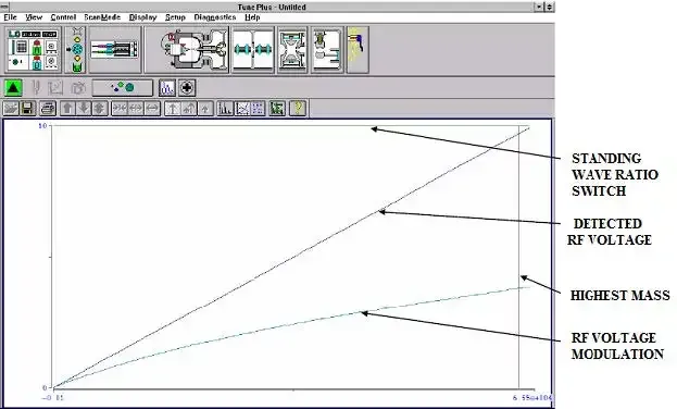
- Click on the Start button. The Graph view should look as displayed in Figure 3 with the following characteristics: the standing wave ratio switch line should be at 10 V over the entire range; the detected RF voltage should be a straight line that begins at the origin and intersects the standing wave ratio switch line near the highest mass line; the RF voltage modulation should be a curved line that begins at the origin and intersects the highest mass line at a value between 3.5 and 4.5 V.
- Inspect the graph view. If the above three conditions are met proceed to the next step. If the conditions are met over part of the range but not all of the range (the curves flatten or change value abruptly), tune the RF voltage frequency as described in the next step and repeat the tuning of the ring RF modulation. If the standing wave ratio switch, detected RF voltage and RF modulation lines are all flat, this indicates a loose connection. Ensure proper connections of the cables and leads. The spring-loaded pin on the RF voltage feedthrough should have proper contact with the ring electrode. Repeat the procedure for tuning the ring RF modulation.
Figure 3. Graph view for ring electrode RF voltage modulation tuning.
- Tune the ring electrode RF voltage frequency.
- In the Test Type box, select Tune RF frequency. The Continuously option button in the How many times group box is automatically selected.
- Click on the Start button. The Graph view displays several tune functions, a frequency cursor, and a frequency window as shown in Figure 4.
Figure 4. Graph view for ring electrode RF voltage tuning.
- Allow the program to make at least five passes. Inspect the graph. The frequency cursor should lie within the frequency window. If this is true, click on the Stop button and exit from the diagnostic program. Otherwise, the ring electrode RF voltage frequency needs to be adjusted manually. Inform the person responsible for the instrument that will perform the necessary adjustments. The adjustment of the ring electrode RF frequency is done as follows:
- Open the left front door of the MS detector.
- Using a Philips screwdriver, remove the air deflector to expose the tuning stud. See Figure 5.
- Using a wrench, loosen the 9/16-in. lock nut that holds the tuning stud in place.
- Using a screwdriver, turn the tuning stud until the frequency cursor lies slightly to the left of the center of the frequency window. (The cursor should shift slightly to the right when the air deflector is reinstalled).
- Tighten the 9/16-in. lock nut.
- Reinstall the air deflector and close the left front door of the MS detector. Make sure that the frequency cursor is still within the frequency window. If necessary, repeat the abovementioned steps.
- Click on the Stop button to stop the ring electrode RF voltage frequency tune program.
Figure 5. Ring electrode RF voltage tuning stud (with air deflector removed).
- Perform diagnostic tests on each of the electronic subsystems (power supplies, API and temperatures, lenses, and RF voltage electronics). From the Diagnostics dialog box, select the subsystem to be tested and click on the Start button to start the diagnostics. The results (Pass or Fail) of the test are displayed in the Testing text box. If the diagnostics indicate a problem, the maintenance procedure indicated by the LCQ diagnostics must be performed by authorized personnel.
ANNEXURE
Nil
REVISION HISTORY
Nil
Popular Posts
New Drug Application (NDA) Process
June 06, 2023
Drug Approval Process in Japan
June 29, 2023
SOP for Handling of Deviation
October 14, 2023
Drug Approval Process in Europe
May 30, 2023
Effective Dossier Management in Regulatory Affairs
June 26, 2023
SOP for System Suitability Test in HPLC analysis and HPLC Documentation
September 01, 2023
SOP for Operation of Shimadzu HPLC (Prominence – i LC – 2030)
October 07, 2023
Most Popular
Footer Menu Widget
Copyright © 2025 PharmaInfo All Right Reserved.
Created By Blogspot Theme | Distributed By Gooyaabi Templates


%20in%20Pharmaceutical%20Development.webp)


..webp)

0 Comments