


.webp)


.webp)

SOP for Routine Maintenance of the Dionex HPLC
OBJECTIVE
This procedure provides a guideline for the routine maintenance of the Dionex HPLC instrument.
Preventive maintenance activities are performed periodically in order to help maintain the quality performance of the instrument and prevent failures during analysis.
SCOPE
The maintenance activities stated herein only apply to the Dionex HPLC instrument. Maintenance of the different instrument parts includes those shown in Table 1.

Table 1. HPLC parts that require maintenance.
HPLC part | Procedure | Frequency |
Autosampler syringe | Replace syringe | if contaminated, damaged or broken |
Autosampler needle | Replace syringe | if contaminated, bent, blunt or broken |
Autosampler needle port seal | Replace needle port seal | if plugged with particulates |
Solvent line filter (sinker) | Clean sinker | monthly |
Replace sinker | annually or when necessary* | |
Pump vacuum online degasser | Clean degasser channels | when necessary* |
Pump | Visual inspection for leakage | when necessary* |
Pump pistons seal | Replace piston seal | if there are problems with pump head leakage or when necessary* |
Deuterium lamp | Replace lamp | if the lamp intensity is too low or if the lamp is defective if the lamp is busted |
Flow cell | Clean flow cell | if dirty |
Fuse | Replace fuse | if the fuse has blown |
* depends on the current conditions
RESPONSIBILITY
Executive – Quality Control– To perform the preventive maintenance activity.
Head – Quality Control – To ensure compliance with the established schedule.
PROCEDURES
Instructions for the Operation of the Dionex HPLC System with UV-Vis Diode Array Detector, SOP for ThermoFisher Scientific HPLC.
INSTRUCTIONS
Replacing the Syringe
Replace the syringe when it is damaged, broken or contaminated and the contaminants cannot be removed by the washing procedure suggested in the Section below (Observation).
Remove the Syringe
- Using water, draw the maximum syringe volume from any sample position desired.
- Turn off the autosampler and disconnect the power cord.
- Loosen the retaining screw of the syringe-drive carriage.
- Carefully twist the barrel of the syringe, unscrewing it from its location.
- Once loose, pull the syringe downwards and remove it.

Figure 1. Syringe compartment.
Install the New Syringe
- Fill the syringe with water and ensure that no bubbles occur in the syringe.
- Place the seal on the syringe to be inserted.
- Put the syringe in the drive carriage and carefully screw the syringe into place.
- Tighten (hand-tight) the retaining screw.
- Turn ON the autosampler. The autosampler performs a self-test.
Replacing the needle of the autosampler
Replace the needle when it becomes bent, blunt, broken or when it is contaminated and the contaminants cannot be removed by the washing procedure suggested in the Section below (Observation).
Note: Before replacing the needle, ensure that the needle is in the needle port.
Remove the needle as follows
- Remove the vial carrier.
- Turn on the autosampler. The self-test will stop and a Home seek failed error message will appear.
- Turn off the autosampler and disconnect the power cord. The needle is now in the highest position above the needle port.
- Loosen the upper enclosure cover that is affixed by four screws. Completely remove the two screws at the rear and loosen two screws at the front. Push the cover to the back. (Warning: Before opening the cover, make sure that the autosampler is turned off and disconnected from the mains).
- Remove the fitting screw of the needle capillary from the fluid block using the supplied 3/16" spanner.
- Remove the retaining screw on top of the needle arm using a 17-mm spanner. While loosening the screw make sure that the needle capillary is situated in the whole of the screw and is not in its lateral slot (See Figure 2). Note: Hold the needle guide to let the spring relax slowly. The needle guide is easily accessible via the sample compartment.
- Before you push up and remove the needle from the needle guide, remove the needle capillary from their 3 guides (on the linear drive, on the MSV enclosure, and on the green printed circuit board (See Figure 2).
- Remove the needle guide.

Figure 2. Parts of the needle capillary
Install the Analytical Needle
- Via the sample compartment, insert the needle guide from below into the needle arm.
- From the top, insert the needle as far as possible into the needle guide.
- Press the needle guide to the top until its thread is visible at the top of the needle arm. Make sure that the horizontal guide pin is in the corresponding cutout of the needle arm.
- Attach the retaining screw and check by applying slight upward pressure whether the needle guide can be moved towards the top. Tighten the retaining screw hand tight.
- Using your thumb and forefinger, bend the needle capillary as close as possible to the retaining screw by 90° parallel to the needle arm away from the sample compartment. (Note: Do not break the needle capillary and observe a minimum of 5mm bend radius.)
- Press the needle capillary into the respective guide of the green printed circuit board on the needle arm, after the next bend (factory-default) into the gray guide at the linear drive and finally into the respective guide at the MSV enclosure.
- Tighten the capillary on the fluid block.
- Close the enclosure cover.
- Install the vial carrier.
- Align the needle port. This is necessary whenever the needle or the needle port has been replaced.
- Go to the Main Menu of the autosampler and select Setup.
- On the Setup menu, select Align Needle Port. You will be prompted to align the needle port using the arrow keys.
- Use either the up and down cursor keys or the arrow keys to increase or decrease the indicated value. The up keys move the needle away from the carrier; the down keys move the needle toward the carrier.
- To accept the modifications, press Enter. Otherwise, select ESC to cancel.
ALSO READ: Checklist for Preventive Maintenance of HPLC
Replacing the Needle Port Seal
Replace the needle port seal when it is plugged with particulates that cannot be removed.
- Remove the Vial Carrier
- Turn ON the autosampler. The self-test will stop and a Home seek failed error message will appear.
- Turn OFF the autosampler and disconnect the power cord. The needle is now in the highest position above the needle port.
- Remove the top part of the needle port using the 10 mm spanner.
- Remove the needle port seal that is located in the top part of the needle port.
- Install the new needle port.
- Using a pair of tweezers, insert the needle port seal into the top part of the
- needle port without tilting the seal. The top of the needle port seal must point to the top of the needle port (See Figure 3).
- Tighten (hand-tight) the needle port to its bottom part.
- Install the vial carrier. Align the needle port, if necessary, following instructions in Section Align the needle port.

Figure 3. Needle port with needle port seal
Cleaning the Solvent Line Filter Frit (Sinker)
- Remove the filter frit from the solvent line.
- Immerse the filter frit in a beaker containing methanol.
- Place the beaker in an ultrasonic bath for 10 minutes.
- Reconnect the filter frit in the solvent line.
Cleaning the Vacuum Online Degasser Channels
- Clean the degasser channels at regular intervals or whenever chromatograms show reproducible ghost peaks.
- Prepare a 20% nitric acid solution in water.
- Replace the column with a backpressure capillary.
- Using the commonly used flow rate for normal operation, rinse degasser channels for 1 hour with 20 % nitric acid.
- Rinse degasser channels with HPLC-grade water until the pH value is neutral.
- Using the commonly used flow rate for normal operation, rinse the degasser channels with HPLC-grade acetonitrile for 2 hours.
Visually inspecting the Piston Seals for Leakage
- Disable active rear-seal washing. On the Configuration menu, under Options, select Rear Seal Wash = No.
- Enable seal washing again. Select Rear Seal Wash = Yes.
- Remove the silicone tube from the detector of the rear-seal wash system (See Figure 4). Shake the tube to remove some of the liquid.
- Reinstall the silicone tube on the detector.
- Set the flow rate necessary to generate a backpressure of approximately 300 bar (30 MPa, 4350 psi).
- Observe the air/liquid level in the silicone tube to evaluate possible leakage. If the level travels the tube, this indicates leakage. If the level remains unchanged, the piston seals seal tightly. If the level rises or falls, it indicates a leak from one or more of the main piston seals. In this case, it might be necessary to replace all piston seals and supporting rings.
- Follow the instructions in Section Replacing the Piston Seals, Replacing the Piston Seals.

Figure 4. A liquid reservoir of the rear-seal wash system.
Replacing the Piston Seals
Replace the piston seals whenever there are problems with pump head leakage and when it is known that the problem is attributed to the piston seal.
Remove the pump heads and pistons as follows
- If necessary, purge the pump to remove toxic solvents.
- Set the pump flow rate to 0.
- Disconnect all fluid connections from the pump heads (See Figure 5).
- Loosen the Allen screws on the two pump heads. Carefully remove the pump heads.
- Carefully remove the bushing of the seal-washing chamber from the piston (including the seal). See Figure 6.
- Remove the bushing with a draining device from the piston unit, using the extractor from the pump´s accessories kit. See Figure 6.
- Loosen the piston retaining screw using the flat-blade screwdriver. Move the piston forward, toward the front cover of the pump, and remove it from the enclosure.

Figure 5. The fluid system of the P680 HPLC pump (See Table 2 for the description of each part).
ALSO READ: Do's and Don'ts: HPLC Analysis
Table 2. Description of the fluidic system of the HPLC pump.
No. | Description |
1 | Piston unit |
2 | Piston retaining screw |
3 | Bushing with draining device |
4 | Retaining screw (DR) |
5 | Rear-seal wash system (piston head bushing) |
6 | Ring seal |
7 | Support ring |
8 | Piston seal |
9 | Capillary between working head and equilibration head (top) |
10 | Outlet valve (includes valve cartridge) |
11 | Valve cartridge (identical to No.14) |
12 | Working pump head without pressure sensor |
13 | Allen screw (I-M4x40) |
14 | Valve cartridge |
15 | Inlet valve (includes valve cartridge) |
16 | Connecting tube |
17 | Equilibration pump head with pressure sensor and purge screw |
18 | Capillary connection to the mixing chamber/purge block or outlet block |

Figure 6. The bushing and the ring seal upon removal of the pump head.

Figure 7. How to remove the bushing (a) extractor (b) piston and bushing with a draining device (c) removing the bushing with a draining device.
- Clean the piston by rinsing the piston with water and then with methanol.
- Rub the piston several times with a dry, lint-free paper towel.
- Remove the piston seals as follows.
- Use a disassembled piston to remove the piston seal from the pump head. Using a dummy plug, close the outlet valve on the working pump head.
- Using a dummy plug, close the boreholes on the equilibration pump head.
- Insert the piston tip into the piston seal to remove the piston seal. If the piston cannot be removed, use an M4 screw and insert the screw into the seal.
- Remove the seal. Note: Replace the support ring if the piston seal in the pump head is replaced.
- To remove the piston seal in the rear seal chamber, remove first the retaining screw on the rear of the pump head bushing. Use a flat-blade screwdriver to remove the screws.
- Remove the seal. Use the piston to push the piston seal out of the bushing.
Reinstall the piston, piston seal, and pump head as follows
- Take the piston in one hand and slide the new piston seal over the piston.
- Insert the piston and the piston seal together into the pump head bushing.
- Remove the piston. The piston seal should remain in the piston head bushing.
- Install and tighten (hand-tight) the pump head bushing retaining screw.
- Install the piston in the pump block.
- Using the flat-blade screwdriver, tighten the piston retaining screw.
- Slide the bushing with the draining device onto the shaft. Ensure correct orientation of the bushing. See Figure 8.
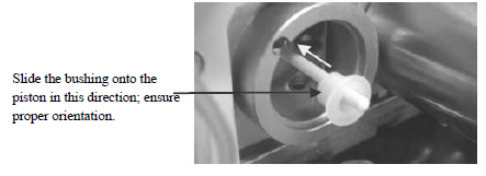
Figure 8. Correct orientation of the bushing with a draining device.
- Slide the complete pump head bushing over the piston unit.
- Slide the new support ring and the piston seal onto the piston.
- Slide the ring seal onto the pump head bushing.
- Slide the pump head onto the piston (turn and push as necessary) until the second piston seal is correctly in place.
- Tighten the pump heads with Allen screws.
- Insert the inlet and outlet valves into the working pump head.
- Attach the capillary connections. Hand-tighten first and then tighten them one-quarter turn using a ¼" wrench.
- Attach the solvent line to the inlet valve.
- Attach the silicone lines of the seal wash system to the corresponding capillaries.
- Rinse the pump thoroughly using at least 30 mL HPLC-grade water or pure
- organic solution. Open the purge block to prevent the rinsing liquid from entering the HPLC system.
- Test the pump for leakage following instructions in Section Testing the pump for leakage.
ALSO READ: Daily and Routine LC Maintenance
Replacing the Deuterium Lamp
Replace the deuterium lamp if the lamp intensity is too low or if the lamp is defective or busted.
Remove the deuterium lamp as follows
- If the lamp is connected to Chromeleon, select the Disconnect command in Chromeleon to terminate communication.
- Turn off the power of the detector and disconnect the unit from the mains.
- From the detector´s left-side panel, remove the removable cover. To open, press in and turn the knurled screw 90° counterclockwise. Open and remove the panel (See resulting Figure 9). Do not bend the Teflon capillary.
- Allow the lamp to cool down.
- Disconnect the lamp by gently pressing either side of the locking plug.
- Using a 2.5 mm Allen key, undo and remove the two lamp retaining screws.
- Remove the lamp carefully.
Install the new lamp as follows
- Insert the new lamp.
- Align the notch on its base with the alignment pin of the lamp housing.
- Replace the retaining screws. Note: Avoid touching the glass tube of the lamp.
- Reconnect the cable.
- Reinstall the removable cover on the detector´s left-side panel.
- Turn on the detector.
- On Chromeleon, select the Connect command to restore communication with Chromeleon.
Note. Let the new lamp to "run in" for at least 24 hours before starting the first analysis.
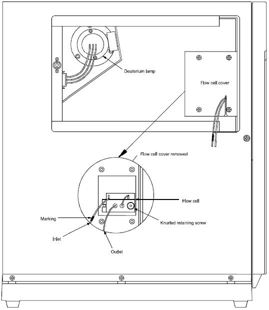
Figure 9. Side view of the detector showing an open side panel.
Cleaning the Flow Cell
Clean the flow cell when it becomes dirty as evidenced by a decrease in detector performance or unusual noise levels.
Remove the flow cell
- If the detector is connected to Chromeleon, select the Disconnect command in Chromeleon to terminate communication.
- Turn off the power of the detector and disconnect the unit from the mains.
- From the detector´s left-side panel, remove the removable cover. To open, press in and turn the knurled screw 90° counterclockwise. Open and remove the panel (See resulting Figure 9). Do not bend the Teflon capillary.
- Undo the four retaining screws and remove the flow cell cover.
- Undo the knurled flow cell retaining screw and carefully remove the flow cell assembly.

Figure 10. Standard flow cell (See Table 3 for the description of each part).
Table 3. Description of the detector flow cell.
No. | Description |
1 | M3x12 screw (DIN 965) |
2 | Heat exchanger |
3 | PEEK tubing (0.5 mm ID) |
4 | PEEK fitting screw (1/16", 15 mm) |
5 | M3x23 screw (DIN 965) |
6 | Lens retaining plate 1 |
7 | Quartz lens |
8 | Flow cell body |
9 | Lens retaining plate 2 |
10 | Flow cell housing |
11 | Single-part hand-tight fitting |
12 | Capillary tube (1.58 x 0.25 ID) |
13 | PEEK double ferrule |
14 | Flow cell body retaining screw |
15 | Fitting screw |
ALSO READ: SOP for Operation of Chromeleon Software
Clean the flow cell as follows. Use gloves when handling the detector parts
Note: To clean the flow cell, follow the steps below and refer to Figure 10 for the part numbers which are in parentheses. When cleaning the flow cell, only the lens retaining plates and the lenses may be removed. Do not attempt to remove the flow cell body (8) from its housing (10). Clean the flow cell body together with the housing.
- Undo and remove the screws (1) and remove the heat exchanger (2).
- Undo and remove the screws (5) and carefully remove the lens retaining plates (6 and 9) and lenses (7). To avoid scratching the lenses, place them on a clean, lint-free cloth or tissue.
- Clean the lenses using a soft, lint-free cloth or tissue and an optical cleaning solution or isopropanol.
- Replace scratched or damaged lenses.
- Clean the flow cell body and housing by rinsing the parts with water, isopropanol, or methanol, or placing the entire assembly in an ultrasonic bath.
- Reinstall the lenses onto either side of the flow cell body so that the plane faces are on the inside.
- Reinstall the lens retaining plates (6 and 9). Tighten the screws (5) carefully and evenly, without excessive force.
- Check the flow cell for leakage before installing them into the unit. Tighten the screws (5) if necessary.
Install the flow cell as follows
- Insert the cleaned flow cell, aligning the notch with the alignment pin of the flow cell socket.
- Reinstall the flow cell cover.
- Reinstall the removable cover on the detector´s left side panel.
- Turn on the detector and restore the communication with Chromeleon using the Connect command.
Replacing the Fuse
- Replace the fuse only when the fuse has blown.
- Turn off the instrument module.
- Disconnect the power cord from its source.
- Using a small screwdriver, remove the fuse cartridge.
- Replace the fuses with fuses of the appropriate ratings.
- Reinstall the fuse cartridge.
- Reconnect the power cord to its source and turn on the instrument module.
Testing the Pump for Leakage
- After performing maintenance or repair work on the fluid connections, test the pump for leakage.
- Close the pump outlet with a dummy plug.
- Set the upper-pressure limit of the pump to 450 bar (6525 psi).
- Turn on the pump and set the desired flow rate until the pressure increases.
- Observe the change in pressure and decrease the flow as soon as the pressure builds up (typically between 100 and 200 bar (1450 and 2900 psi).
- When the pressure reaches 350 bar (5075 psi), shut off the flow and observe a drop in pressure. A properly functioning pump should lose less than 15% of its pressure within 10 minutes after being shut off.
- In case of leakage, visually inspect the piston seals for leakage and tighten the leaking connections, if necessary.
- Reset the upper-pressure limit to the value used before the test.
Observations
When contamination is present and needs to be remedied, the following wash procedure is suggested. When using methylene chloride or hexane, flush first with isopropanol before returning to the aqueous mobile phase. After washing with the solvent, check (for example, by performing a blank injection) whether the contaminants were removed before proceeding to the next wash solvent.
- When using buffers, replace the buffer with water and flush the system with water.
- Flush with 100% methanol.
- Flush with 100% acetonitrile.
- Flush with 75%acetonitrile-25%isopropanol.
- Flush with 100% isopropanol.
- Flush with methylene chloride.
- Flush with 100%hexane.
In cases where scheduled maintenance is delayed, instrument use may be put on hold only if its use is critical to the analysis and if the instrument shows uncharacteristic behavior.
Moreover, a notice must be posted about the reason for the delayed maintenance and the probable date for carrying out the maintenance.
Annexure
Maintenance Logbook
Date | Name | Maintenance Details |
|
|
|
|
|
|
|
|
|
|
|
|
|
|
|
|
|
|
|
|
|
|
|
|
|
|
|
|
|
|
|
|
|
|
|
|
|
|
|
|
|
|
|
|
|
|
|
|
|
|
|
|
|
|
|
|
|
|
|
|
Revision History
Nil
Posted by PharmaInfo

0 Comments