


%20and%20Drug%20Registration%20Process%20in%20Uganda.webp)


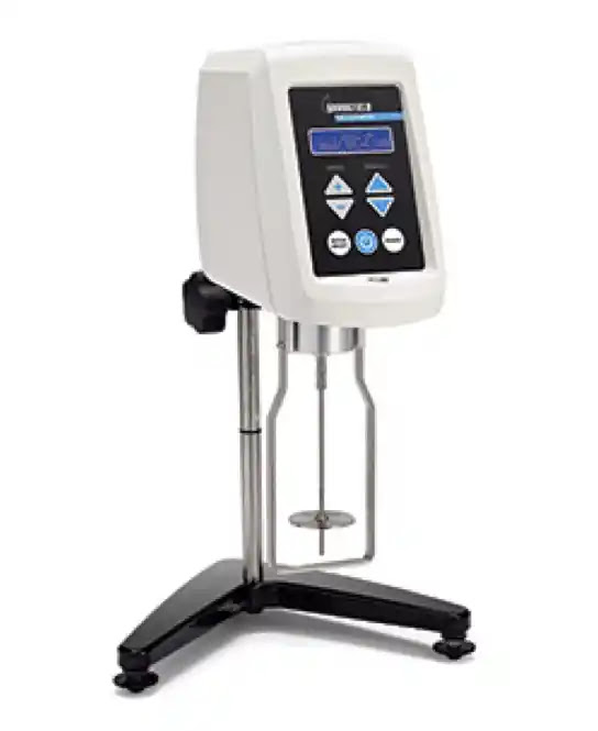
SOP for Operation & Calibration of Brookfield Viscometer (DV – II + PRO LV)
OBJECTIVE
To lay down the procedure to be followed when operating the Brookfield (DV – II + PRO LV) viscometer.
SCOPE
The procedure applies to the Brookfield (DV – II + PRO LV) viscometer located in the QC laboratory at PharmaInfo.
RESPONSIBILITY
It is the responsibility of every individual operating the instrument to follow the outlined procedure.
It is the responsibility of the Manager QC/QA Manager to ensure that the procedure is followed without deviation.
PROCEDURE
Operation
- Adjust the instrument level using the two leveling screws on the base and make sure that the bubble on top of the viscometer is centered within the circle. Note: Check the level periodically during use.
- Connect the RTD probe to the socket on the rear panel of the viscometer.
- Connect the power cord to the socket on the back panel of the viscometer and make sure that the AC power switch at the rear of the viscometer is in the OFF position.
- Turn the power switch to the ON position and allow it to warm up for 10 minutes before performing auto zero.
- The screen will display the name of the instrument and its version of the operating firmware and a two-digit alphanumeric code that indicates the model number.
- The screen will then display “REMOVE SPINDLE, PRESS ANY KEY” after 10 seconds.
- Remove the spindle and press any key. The viscometer will flash “AUTOZEROING”.
- After approximately 15 sec, the display will show “REPLACE SPINDLE, PRESS ANY KEY”.
- Attach the required spindle for the specific test and dip the IRTD probe into the sample then press any key.
- The display will show the cP 0.0 (on the left corner) OFF RPM (below the CP), the temperature i.e. 20.1°C (on the right corner), and the torques percentage % 0.0 (below the temperature).
- Press the SELECT SPINDLE key and it will temporarily display the current selected spindle in place temperature and cause the character S to blink.
ALSO READ: SOP for Sampling of Packaging Materials
- Press the UP or DOWN ARROW Keys, While S is blinking, select the desired spindle code then press the SELECT SPINDLE key again.
- Press the SET SPEED Key, then press the UP or DOWN key arrows. Will cause the RPM letters to blink.
- Select the required speed by pressing the UP or DOWN arrows while the RPM is blinking. The selected speed will blink for 3 seconds then it stops.
- Dip the guard leg with the spindle into the sample slowly and make sure no air bubbles are trapped.
- Press the MOTOR ON/OFF-ESCAPE Key to set the motor on or to stop the motor.
- The display will show the viscosity on cP, the speed on RPM, the temperature, and the torque percentage %.
- To get the maximum calculated viscosity (full-scale reading) possible with the current spindle/speed, press the ENTER AUTO RANGE Key.
- The display will show EEE on both the cP and torque % when the operation is out of range.
- The display will indicate “__________ C” if the RTD temperature probe is not connected.
- When the torque % is below 10 it will keep blinking. Nonetheless, record the readings on the display.
- Press the MOTOR ON/OFF-ESCAPE to stop the motor.
- Remove the spindle and guard leg from the sample and clean the RTD probe spindle and guard leg with distilled water.
Calibration
- The Brookfield DV – II + Pro is to be calibrated once every six months, after repairs, before use without a guard leg, and/or before use with any other beaker but the 600ml low form griffin beaker.
- Brookfield silicone fluid viscosity standards with values: 10, 500, 1000, 12500 & 60000cp using respective spindles and record results on Attachment -1.
- Set up the viscometer as per the operating procedure mentioned above on a level firm bench.
- When carrying out the calibration process ensure the following;
- The calibration log book is available.
- The viscometer is set according to operating instructions.
- The water bath is stabilized at a test temperature of 25°C.
- The guard leg is clean and attached.
- Only LV 1, 2, and 3 spindles (61, 62, and 63 respectively) are to be used.
- Only the low-form Griffin beaker is used.
- Select one viscosity standard fluid and place it in the low-form griffin beaker.
- Lower the DV-II + Pro into the measurement position.
- Attach the spindle to the viscometer while avoiding trapping air bubbles beneath the spindle by immersing it at an angle and then connecting it to the viscometer.
- Measure the viscosity and record the results as per Attachment -1. Note: The spindle must rotate at least five times before readings are taken and the value of torque should be more than 10%.
- Repeat the procedure for the remaining silicone fluid viscosity standards.
ATTACHMENTS
Attachment-1: Calibration report viscometer
REVISION HISTORY
Nil
)
Posted by PharmaInfo

0 Comments