


%20in%20Pharmaceutical%20Development.webp)

.webp)


.webp)

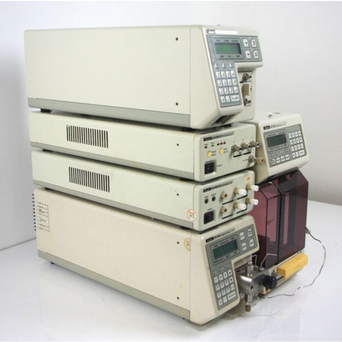
SOP for High Performance Liquid Chromatography (Jasco)
PURPOSE
The purpose of this SOP is
- To define the operating procedure.
- To define the precautions to be taken during handling.
- Cleaning procedure and maintenance.
SCOPE
This SOP is applicable for the operation, handling, cleaning, and maintenance of the High-Performance Liquid Chromatograph. Make: Jasco Model: UV-975, PU-980
RESPONSIBILITY
- To organize the Job training program for the implementation of SOP.
- To monitor overall activities in adherence to the compliance of approved SOP.
- To arrange necessary servicing and maintenance.
- To check the recorded documents for their correctness, accuracy, and completeness.
Section in-charge
- To operate the instrument as per SOP.
- To record the observations as per SOP.
- To maintain the documents as per SOP.
Wear an apron, cap, and company footwear.
PROCEDURE
Startup
- Clean the High-Pressure Liquid Chromatography (HPLC) system and surroundings.
- Ensure that the system consists of the following equipment
- Liquid Chromatograph (Isocratic Pump) – Model PU-980 Make: Jasco
- UV VIS Detector - Model : UV-975
- Software - Borwin
- Select the prescribed column and connect in the specified direction i.e. in the direction of the flow arrow/sign marked on the column, The column outlet end is connected to the inlet of the detector, which in turn is connected to the ‘Drain’ through the tubing.
- Ensure that the mobile phase flow is in the following direction.
- Ensure that UPS is working.
- Connect the power supply and switch ON the mains.
- The instrument is ready for calibration or use.
Operation
Pump
- Ensure that, the instrument is calibrated and the start-up procedure is followed.
- Turn the power switch, located at the lower left of the front panel, to the ‘ON’ position.
- The LED display glows on and it follows diagnostic tests.
- Wait till initialization is completed.
- Press the “EDIT / ENTER” or the ‘2’ key. The flow value on the display starts blinking then press the EDIT / ENTER key.
- Set the flow at 0.2 ml/min, using the numerical keys on the panel, and again press the “EDIT / ENTER” key.
- Press the ‘5’ key. The value of P. MAX will start blinking. Set the value at 500; press the “EDIT / ENTER” key.
- Press the ‘6’ key. The value of P. MIN will start blinking. Set the value at 0; press the “EDIT / ENTER” key.
- Ensure that the end of the inlet tubing of a pump is in the reservoir containing at least 50 ml filtered and degassed methanol (HPLC Grade).
- Open the purge valve by rotating the knob in an anticlockwise direction.
ALSO READ: SOP for Operation of Chromeleon Software
- Press the ‘PUMP’ key. The orange pilot lamp indicates that the pump is on.
- The methanol flows through the pump and is drained out from the drain tube connected to the outlet of the purge valve.
- Allow running methanol for 5 minutes or till any air bubble produced in the tube is drained out.
- Press the PUMP key. The pilot lamp is off.
- Close the purge valve by rotating it in a clockwise direction.
- Press the ‘2’ key. And set the flow at 0.2 ml/min. Press the “ EDIT / ENTER” key. Press the PUMP key.
- The valve on the monitor screen indicates the actual pressure.
- Gradually increase the flow with the interval of 0.2 ml/min to 1.0 ml/min.
- Allow running for 10 minutes.
- Gradually decrease the flow with the interval of 0.2 ml/min; to 0.0 ml/min.
- Press the PUMP key. Remove the tubing from methanol and place it in the reservoir containing filtered and degassed (sonicated) water for HPLC.
- Follow the instructions as per points 11 to 18.
- Allow running for at least 20 minutes. Then decreases the flow. And press the ‘PUMP’ key.
- Replace the water with a reservoir containing the Mobile phase.
- Follow instructions 11 to 18 and increase the flow to the specified flow rate.
- Allow the run at the specified flow rate for at least 15 minutes or as specified in the individual monograph so as to equilibrate the system with the mobile phase.
- The system is now ready for injection.
- Inject the samples as per individual specifications.
- After completing all the injections, switch off the detector, and make entries in the Usage Log.
- Gradually decrease the flow with the interval of 0.2 ml/min to 0.0 ml/min.
- Press the PUMP key. Remove the tubing from the mobile phase and place it in the reservoir containing filtered and (degassed) sonicated water for HPLC.
- Allow running for at least 240 minutes. Then decrease the flow and press the ‘PUMP’ key.
- Replace the water with a reservoir containing Methanol.
- Allow running for at least 20 minutes. Then decrease the flow and press the ‘PUMP’ key.
- Switch off the Pump.
- Switch off the mains.
Detector
- Turn the Power switch, located at the lower left of the front panel, to the ‘ON’ position.
- The LED display glows on and it follows diagnostic tests.
- Wait till initialization is completed.
- Press the “EDIT / ENTER” or the ‘1’ key. The value of the wavelength on display starts blinking.
- Enter the specified wavelength using the numerical keys.
- Press the “EDIT / ENTER” key 2 times or press the ‘2’ key. The value of the range on display starts blinking.
- Enter the specified range using or keys. Again press the EDIT / ENTER key.
- The absorbance value will be displayed on the screen.
- The system is now ready for analysis.
Integrator (NT Based Software)
- Switch on the computer in which the Software is installed.
- Wait till the initialization is complete.
- Activate the software by clicking on “BORWIN” on the Desktop.
- Wait till the software undergoes start-up procedures.
- Enter the specified ‘OPERATOR’ Name, and ‘USER’ name, and then click ‘OK’.
- The screen now displays the software window with the selected ‘USER’.
- Click on the ‘RUN’ key, then monitor Base Line, and select the specified system.
- Enter the appropriate information in the displayed chart. i.e. Run Name, No., Run Length and run information.
- Click the ‘RUN’ key, and the screen will display, a chromatogram showing the ‘Waiting’ status. The system is now ready for analysis.
Analysis
- Use only HPLC-grade solvents for analysis.
- Use only calibrated, clean, dry glass apparatus.
- All the solutions that are entering the HPLC System i.e. water, mobile phase, etc. must be filtered through 0.4 μ membrane filter paper, and properly degassed.
- In the case of the mobile phase containing buffer, it is essential to give water washing to the column prior to and after running the mobile phase.
- Prepare the sample and standard solutions as mentioned in the specifications.
- Ensure that the HPLC system is equilibrated and ready to start.
- Take a clean, dry syringe. Rinse it with water in case of mobile phase containing buffers, or with the mobile phase.
- Remove the red cap of the Rheodyne injector port.
- Ensure that the injector is in the ‘Load’ position.
- Suck water / mobile phase in the syringe, ensuring that no air bubble is trapped in the syringe.
- Inject water / mobile phase in the loop. Rinse the port with water 5 times.
- Inject the mobile phase or the solvent system used for sample preparation and turn the injector downward i.e. in the ‘Inject’ position, the channel on the screen gets activated and shows the ‘Run in Progress’ signal.
- Turn the injector port on the ‘Load’ position.
- After completing the injections again rinse the loop with water and then with Methanol.
- Preserve the column in Methanol.
ANNEXURE
Nil
REVISION HISTORY
Nil
)
Posted by PharmaInfo

0 Comments